|
Making a custom mold for a fused and slumped glass plate
Joseph Stoltzfus
March 19, 2007
Commercial molds for slumping glass often are based on
simple geometric forms such as circles or squares. Many glass artists
prefer these, perhaps because simple shapes seem to avoid any competing
esthetically with the glass design.
I wanted to investigate other shapes that would keep a
feeling of simplicity but also be felt as something different from a
customary design. But it was important to limit any new design to one
that could be implemented in a home shop.
It is quite possible to use a found object as the master
object, but since I have a basic woodworking shop I elected to make the
master and the mother mold out of medium density fiberboard (MDF). As a
first project, I decided to make a plate with a flat rim and a slumped
depth of 3/8 in.
My procedure for laying out the desired shape, making a
master object, making the mother mold, and making the slumping mold are
described in this paper. The mold has been used twice, and pictures of
the results will be added when available.
For the slumping mold I chose Best Mix Mold Mix, a
proprietary product sold by Aquila Glass School. I mixed and cast the
material according to the guidelines provided by the vendor.
I bought the Best Mix from Aquila Glass School. Their
current address is
Aquila Glass School
1628 N Columbia Blvd
Unit A
Portland, OR 97217
503-240-9449
www.aquilaglassschool.com
Look on the website (either one) for extensive
information about using the Best Mix Mold Mix. They have lots of
experience, and they have expanded their website since I began this
project.
|
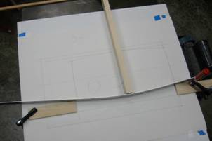
After choosing
an approximate design for the mold and plate, I laid out the
curved sides on paper, drawing the lines along a flexible metal
ruler pushed against clamped stops on a drawing board.
The same method
was then used to draw the same curve on a piece of 1/8-in MDF. |
|
 |
|
The MDF was cut
near the line using a band saw (a coping saw could be used
instead) and then shaped with a block plane and sandpaper to
make my standard curved rule.
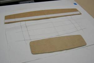
The photos the
full-size drawing of the plate, along with the full size
template of the top of the slumping depression for the mold. The
template was laid out by using the full-size drawing and the
curved rule, and the corners were marked along the edge of a
penny. |
|
 |
The 1/8-in MDF template was shaped by sawing and sanding,
by the same method used for the curved rule. Because the material is so
soft, in a future project ¼-in MDF would be preferred.
To make the master, a 3/8-in stack of MDF was laminated
from layers of MDF. The template was then used to mark the stack,
indicating the top of the slumping depression in the finished mold. The
stack was cut just outside the line on the band saw.
The template was then attached to the top of the stack
using double-sided carpet tape.
Although I used a router to shape the MDF master, it
could be accomplished with hand tools.
|
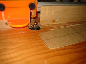
This is the
router table used to cut the master. The router bit is a 45-deg
bevel cutter with a guide bearing. The template was on top of
the laminated stack of MDF, which is not shown. The router bit
was adjusted to let the guide bearing run on the template as the
cutter made a beveled edge on the master.
|
|
 |
|
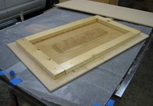
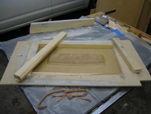
This is the
mother mold ready for filling with the Best Mix Mold Mix. The
mold is placed on a level tabletop; I used a table saw. A
covered the table with wax paper to control the mess; the mix
sticks to everything just like concrete. The master is seen
glued in the center of the bottom board (made of ¼-in MDF), and
the sides are confined with ¾-in wood dams to make a casting
box. The dams are cut at a 5-deg angle to ensure that the
completed slumping mold can be withdrawn. The dams are attached
with woodscrews. |
|
 |
It is necessary to seal the surfaces of the mold box to
prevent water from soaking into the MDF, which would damage the box and
remove water from the mix before it had time to solidify. The varnish
also serves as a release agent, so the mold does not stick to the box
when it solidifies.
I sanded the inside of the box with 220 grit abrasive
paper, wiped out all the dust, then applied four coats of marine varnish
from the hardware store (Ace). I let each coat dry for about 24 hours,
and sanded again after each coat except the last. I was especially
careful to seal the crack where the master was glued to the bottom of
the mold box. Note that the bottom of the mold box meets the surface
that becomes the top of the slumping mold.
To avoid having water from the mix run under the dams, I
sealed the boundary between dam and bottom board with a strip of
modeling clay along two sides, and soaked extra varnish into the gap on
the other sides. Neither proved to be necessary.
I estimated the required amount of mix by calculating the
volume of the box. I could do this because the box is very regular, and
I ignored the volume of the master to ensure I would have a little extra
material. For an irregular shaped mold I would have filled it with dry
rice and then measured the rice in a box or with a cup measure. My
estimate for density of the powder was 19 cu-in/lb.
Shortly before preparing the mold mix, I applied a second
release agent (PAM No-Stick Cooking Spray with Olive Oil).
|
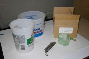
The mix was
prepared by combining measured quantities. I weighed out 72 oz.
of the Best Mix powder into a 5-qt. plastic bucket like the one
in the background. The mix comes from the supplier in a plastic
bag inside the box. I weighed 16 oz. of lukewarm water into the
smaller bucket. The scales was a spring balance I bought at a
flea market. |
|
 |
The ratio of powder to water followed the vendor’s
recommendation, which was described as” not absolute”. I mixed the
materials into a slurry in the larger bucket, adding water to the powder
a few ounces at a time while stirring with a stick. I stopped adding
water when the slurry seemed almost liquid; I could pick up a bit on the
flat stirring stick, but I was afraid to add more water. It was about
what I remember from watching workers pour concrete. Since I had 3 oz.
of water remaining, I had a ratio of 4.9 parts mix to one part water by
weight.
I stirred the mixture for five minutes, enough for
thorough wetting but still allowing time to pour the mold before the mix
began to set. Do not shorten the five minutes, because complete wetting
of every particle is essential.
|
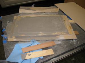
The box was
placed on the table and leveled using wooden wedges. The mixture
was poured into the mold box and leveled with the scrap of
lumber (the screed) behind the box.
The 4.5 lb of
powder with 13 oz. of water proved to be just enough. I allowed
5% extra; I should have allowed 15% extra.
When the box was
filled, I covered it with plastic wrap and left it to set for 24
hours. |
|
 |
I intended to place nails in the corners to maintain vent
holes, to prevent air being trapped and blowing bubbles when the mold is
used. But when the mix was first poured, it was too soft to support the
nails upright and when I returned 3 hours later the mix had set.
|
This shows the
box after the mold was removed from the casting box. Although a
5-deg draft was allowed in the dams, I needed to remove two
sides that were stuck to the mold because of the modeling clay.
One of the dams was stuck to the base, probably because of the
varnish run under the dam, and it had to be pried off.
There was no
damage to the mold.
The dam can
easily be replaced if the box is used again. |
|
 |
|
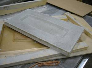
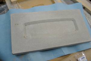
The mold is
shown after it was removed from the casting box. The surface was
very smooth, except for two very small divots in the upper flat
surface. These will be filled with modeling clay when the box ix
used for slumping.
It was clear
that air would be trapped in the corners when slumping, so it
was necessary to drill vent holes in the completed mold. |
|
 |
In future I will devise supports to position the nails
immediately upon pouring and support them until the mix has set.
|
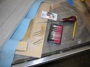
These tools were
used to drill vent holes.
The tools
included a 3/32-in. masonry bit, a 5/64-in. diamond burr made
for a Dremel tool, a set of 20 inexpensive diamond drill bits
from Harbor Freight, and a sharp pointed awl.
Instead of a
Dremel tool, I used an ordinary cordless drill run at low speed.
|
|
 |
|
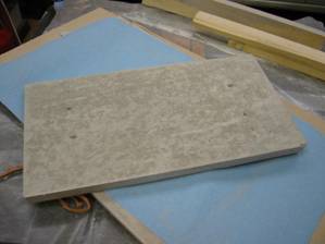
Holes were
drilled from the back and from the front. This picture shows
holes drilled using the 3/32-in. masonry bit.
I was careful
not to drill so far as to break into the bottom of the mold. The
drill worked best at low speed, and it was slow enough to permit
checking the depth frequently. The mold mix is quite
homogeneous, and could be drilled slowly. |
|
 |
|
The holes were
then drilled with the diamond bits from both inside and outside
until they almost met. Forcing through with the awl then
completed them.
This was a
delicate and nerve-wracking procedure, but you can see that the
resulting vents appear centered in the bottom corners of the
slumping depression and have not chipped out significant divots. |
|
 |
Before use for slumping, it is necessary to cure the mold
at high temperature to remove all traces of moisture. It is best first
to let the mold dry in air for a reasonable time. I let it dry in a
living space at 70 deg F and 50% relative humidity for about three days.
Then the mold was cured on the following schedule:
Mold Cure Schedule
|
Ramp (deg F/h) |
40 |
55 |
75 |
9999 |
|
To (deg F) |
225 |
400 |
1400 |
Room |
|
Hold (hr) |
2.00 |
1.00 |
0 |
0 |
|
This is a fused
two-layer item ready to be placed on the mold for slumping. The
base layer is 3-mm clear and the top layer is 3-mm color. The
top layer was cut about 2 mm smaller all around than the base.
The curves were cut using a curved template. The base was cut
first and used to draw the shape on a sheet of drawing paper,
and then cutting guide marks were placed on the paper to aid in
positioning the colored piece and template.
|
|
|
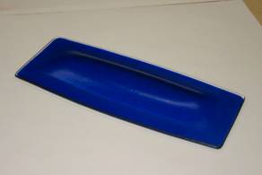
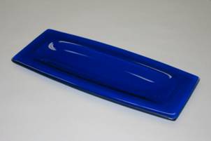
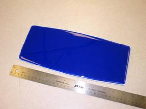
Above are bottom and top views of the two-layer item
after slumping. The bottom surface, which was in contact with the mold,
has an excellent smooth finish. The inside is fire polished as expected.
In future I would use a slightly longer slump time to make the outside
bottom flat.
Results:
The fully cured mold appeared to be in good condition and
was free of cracks. Surface was smooth throughout except for two small
divots described above. These were filled with modeling clay when used
for slumping for the first test, but were ignored for the second test.
There were numerous hairline surface cracks, but these did not affect
the integrity of the mold and were anticipated based on information from
the vendor.
The first piece slumped was a single layer of iridized
black glass slumped iridized side up. The firing schedule for this item
was made fairly short because of the single layer. The mold showed no
damage whatever in use. A second piece was fused and slumped, as shown
in the photos above. No kiln wash was applied for either piece, and was
not needed.
Conclusion:
This project demonstrated the use of Best Mix as a
reliable material for making custom slumping molds. It can be used in a
home shop with simple materials and tools. I will use it for further
exploration of custom forms.
|